Intro/Goals
The core reason for the creation of this project was to fulfill Cal Poly's senior project requirement and the idea went through a number of iterations before coming to the final idea of a pacemaker track-bot. The ultimate goal of the project is to create an autonomous robot that uses a combination of sensors and cameras to navigate a landscape at a fixed speed and distance to service its users.Iteration Process:
- Person Following Robot
- This idea ended up being the closest to our final vision and gave us the most groundwork to build upon.
- The core functionality was to serve as a mobile carrier of items, for example in the form of a cart in a supermarket, or a transporter of sports items for families and soccer moms.
- Overhead Cam-Bot
- This can be described more as a collection of ideas rather than a single fully formed idea.
- One of these ideas centered around a soccer playing robot such as the ones used in RoboCup competitions but in a much more trimmed down capacity that would use overhead vision processing to determine its pathing.
- Another idea was a Roomba-like device that used overhead vision processing to figure out its pathing but we figured Roomba itself likely had that market cornered.
- Grub-Hub Interception/Last Mile Delivery Bot
- The idea for this robot came from the recent introduction of GrubHub Campus Dining delivery robots (as outlined in this article) and the limitations of their delivery capabilities.
- The idea was to extend the range of delivery for these robots as they were primarily used to reach central delivery locations that people would have to walk to in order to retrieve the food from their respective robots. In effect, we would want our robot (which in the ideation process was going to be a flying drone) to take the food from the robot and enter buildings or more crowded areas and deliver the food directly to the customer so they wouldn’t have to lift a finger. Unfortunately, flying drones were out of the picture, (as I’ll expand upon shortly).
- Autonomous Flying Drone as Security Robot or Directions/Guide
- In effect this drone could aid visitors, freshman, or just less traveled campus members to safely get around campus.
- This robot would require mapping to find the fastest routes, and a number of sensors and onboard processors to control it’s own flight process and avoid collisions.
- For nighttime flight thermal cameras, flashlights, and the like would be required alongside GPS and calling services to ensure safety, which was a lot of heavy compute that ultimately made us reconsider a flying drone based robot.
- Flying bots ultimately weren’t going to work because of the numerous considerations that would need to be made that would be far more complex than just a driving robot.
Final Idea
The finalized idea ended up being a combination of the mobile storage robot and the person following guide/security robot in it's form factor and compute requirements. In effect we want to be able to set a distance and pace that we want the user to complete the distance at, and the robot will then autonomously drive at the given pace and avoid collisions. The fully realized version of this project would also entail an app that would allow the user to interact with the robot directly (rather than using the terminal that we currently feed specific flags to perform the way we want it to).BOM (Bill of Materials)
| Part | Part Selected | Quantity | Price (per item) | Price (no ship/tax) | |
|---|---|---|---|---|---|
| Processor | Raspberry Pi 5 | 1 | 44 | 44 | |
| Webcam | Playstation Camera | 2 | 25 | 50 | |
| Battery | LiPo 5000 mah (2 pack) | 1 | 55 | 55 | |
| Motor | Pololu 10:1 Metal Gearmotor | 2 | 0 | 0 | |
| Motor Controller | HiLetGo 43A Motor Controller | 2 | 11 | 22 | |
| Screws | Negligible | 0 | 0 | 0 | |
| Lidar | RPLidar A1M8 | 1 | 85 | 85 | |
| Speaker | MakerHawk 3 watt 8 ohm | 1 | 12 | 12 | |
| Wheels | Pololu 90mm (2 pack) | 1 | 8 | 8 | |
| Buck Converter | DWEII 12V to 5V Converter | 2 | 15 | 30 | |
| Terminal Block | Joinfworld 35A Terminal Block | 2 | 9 | 18 | |
| Base Plates | 1/4” Wooden Slabs | 3 | 0 | 0 |
CAD (Creation of Models for Manufacturing)
After we had decided on a finalized set of components for our robot we were able to start designing the relevant components we would need to begin manufacturing. We settled on simple wooden plates for structural components as we wanted to focus more on the software component than mechanical design component. We also designed a number of 3D printed components that serve as support material and fasteners for all of the valuable electronic components. The current state of that CAD is depicted below: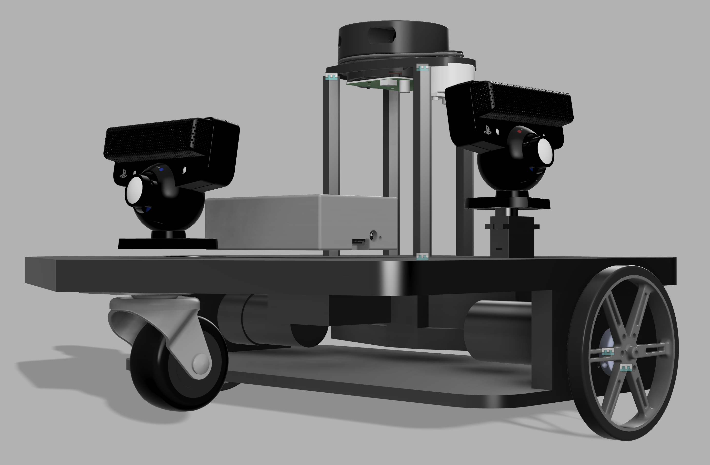
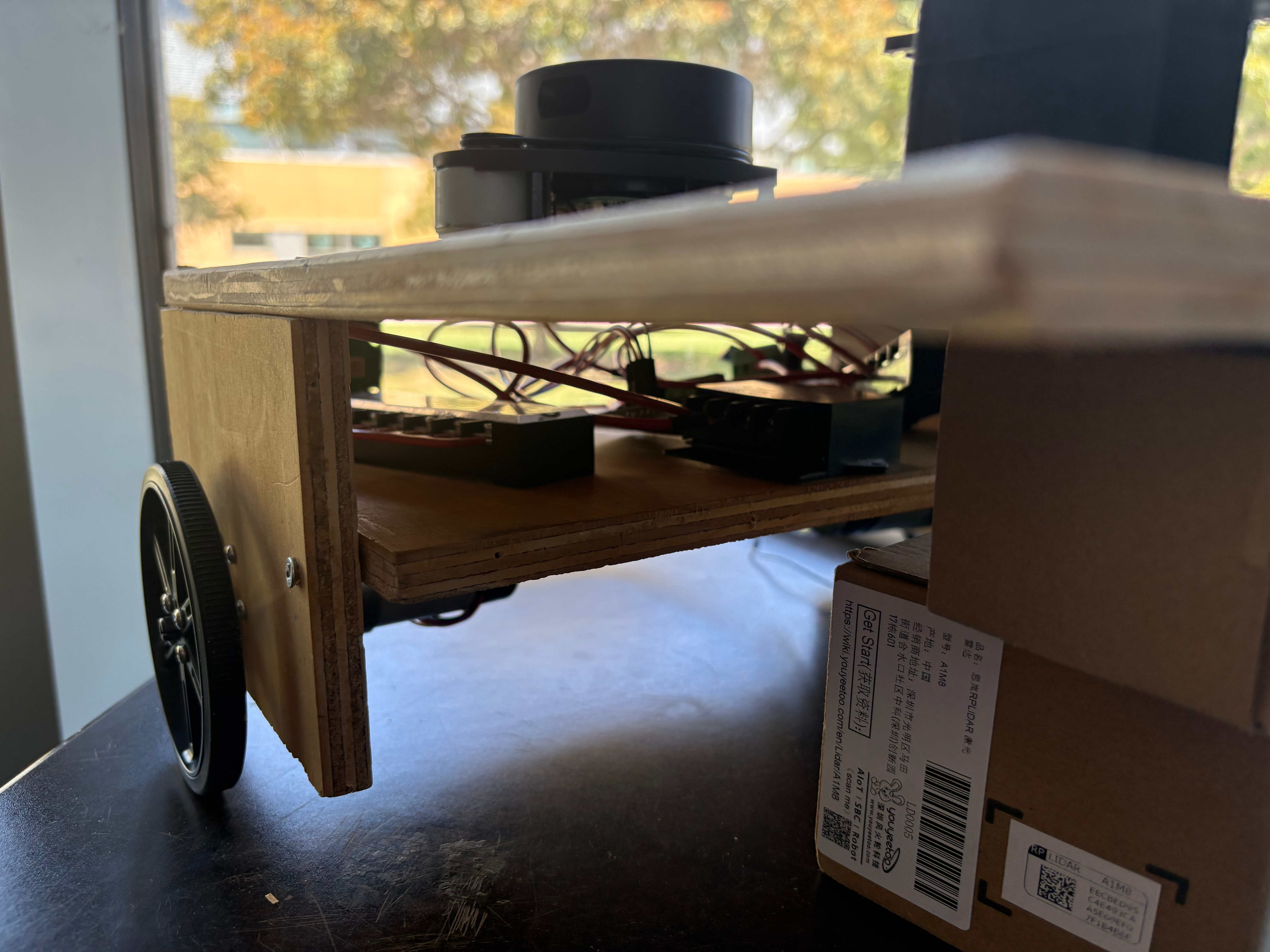
Manufacturing, Assembly, and Debugging
This was supposed to be an exceedingly fast and straightforward step in the process, but of course as all engineering tasks go that was not the case. The initial manufacturing of all of the wooden planks went pretty seamlessly, but all of the electrical wiring posed a serious threat. For starters, I had overlooked how we were going to power the Raspberry Pi we were intending to use for all of the processing and control on the robot. I assumed just a standard 5v buck converter from our terminal block would do the trick, but there are very specific USB-C specs that the Pi requires. Luckily, I had a portable charger that met the specifications, and that has done the trick up until this point. If we have time at the end of the project we will look into a more elegant solution, but with only a few weeks left I find it rather unlikely that we will be able to implement a better solution than the current one. Here's the current mechanical state of the robot: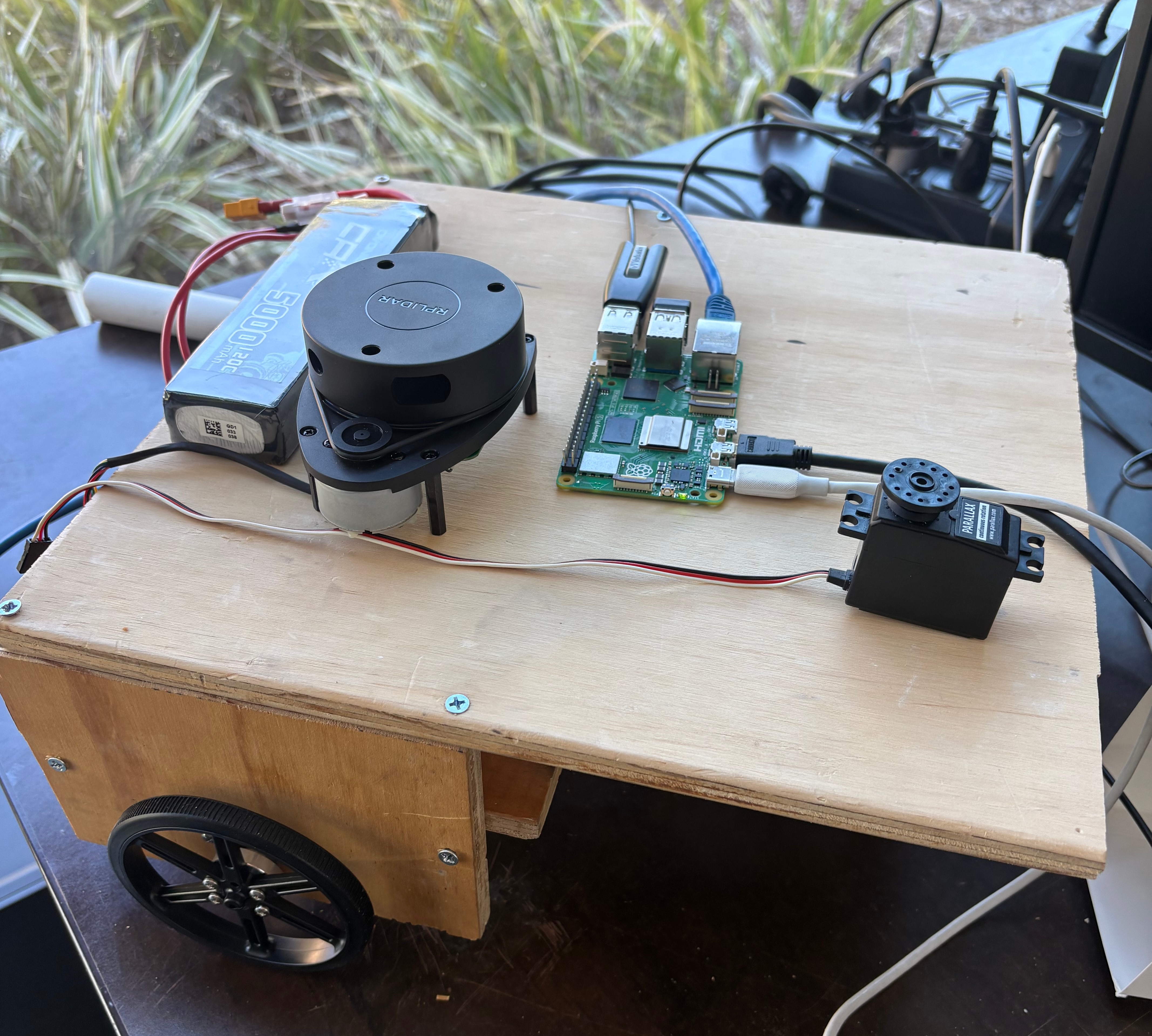
There was also a strange (and to this point not reproducible) issue one night where our motor controllers simply would not respond to any signals. We debugged this issue for hours upon hours, and eventually deduced that we must have somehow fried the motors with improper circuitry. I ordered some replacements as they were so cheap, and when they arrived and I intended to install them, I figured, why not rewire and rewrite the current drive test code just as a final sanity check on the existing motor controllers. Lo and behold that worked as shown by our current 60% drive forward for 10 seconds video included below. The current state of the robot is that it just needs the remaining 3D printed components installed and then it will be a purely software focused approach for the remaining month or so of this project’s timeline. We have a fairly accurate human tracking program that runs on the PS2 camera we’re using on the Pi using OpenCV libraries, but it needs fine tuning and we will soon also begin using the LiDAR alongside yet to be developed PID assisted drive code to make our robot drive autonomously. Here’s a link to the work in progress GitHub repository.
Trackbot; Post-Mortem
I never came back to update this project as it was progressing given the immense amount of work that came with it and wrapping up my senior year of college (as I'm sure you can imagine dear reader). That being said we were able to get the project running and to a functional (enough) state given our original intentions for the project. In effect the Trackbot in its final form would spin in a circle autonomously until it identified a human via the autonomous classification we added to our scripting. Once it did, it would drive towards that human until it reached a certain distance, and then would stop about 2 feet away. If the identified human stepped back or otherwise increased the distance the Trackbot would drive at the identified individual once again. If the individual moved out of the frame of vision for the Trackbot, it would pause and attempt to relocate the individual, but after a custom-set delay, it would start its spinning identification process once again to find a new target or otherwise relocate the individual who moved out of frame. I've included some footage of the project working below, as well as embedded our report deep diving into this project a bit more.